On completion of this stage you should be familiar with the following concepts:
|
Modeling notions: |
Data-element, Data Types, Flow, Slot, Display Data-element, Ancestor Reference, Reserved Names, Prototypes |
|
Modeling techniques: |
Retrieving user input from the display, Storing data in a database table. |
|
Useful process templates: |
Sequence, Insert |
In this stage you will model some basic application logic - retrieving the requisition description entered by the user (through the popup form) and saving it in a database table.
This stage’s modeling should be performed in the Tutorial 2-3 project, you imported at the end of the previous stage.
In the previous stage we learned how to model a form for simple data entry. We mentioned that one crucial thing was missing – saving the data entered by the user.
So now, let's model the saving of the requisition’s description when the user clicks the Submit button.
As mentioned above, Tersus modeling employs a zoom-in technique in which application logic is defined "inside" the display element which invokes it. In our case, saving of the requisition’s details should be performed when the button is clicked, so it will be modeled inside the Submit button.
Zoom into the Submit button by double-clicking on it in the model editor (or in the Outline view).
We will now define a data structure to store the details of a requisition:
Select the Data
Types/Database Record template (![]() )
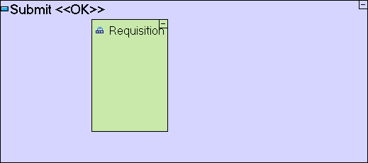
and drop it into the button. Name it Requisition.
)
and drop it into the button. Name it Requisition.
A data structure is a collection of data items (either “primitives” like a number or a date, or other data structures). Data structures appear in the model as gray rectangles.
You may have noticed a Data Structure template appearing next to the Database Record template in the Palette. The two templates are practically identical, except for the fact that a Database Record structure is automatically associated with a matching database table, and since we would like the Requisition data to be stored in the database, as we will see later in this stage, we are basing it on a Database Record.
The Submit model should look similar to the following:
Next we should define the fields comprising the data structure. To insert data elements into the data structure, we simply drag the appropriate data types (Number, Text, etc.).
Select the Data
Types/Number template (![]() )
and drop it into the Requisition
data structure. Name it Id.
)
and drop it into the Requisition
data structure. Name it Id.
Select the Data
Types/Text template (![]() )
and drop it into Requisition
as well. Name it Description.
)
and drop it into Requisition
as well. Name it Description.
The Requisition data structure should look similar to the following:
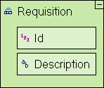
The Requisition data structure now contains 2 fields: Id, which is to be an automatically-generated unique identifier for each requisition, and Description, which is a free text description of the requisition as entered by the user.
As explained previously, Id must be an automatically-generated, unique identifier. It must be unique, because we don’t want any two requisitions to have the same identifier.
This can be accomplished by using the Sequence Number template:
Select the Database/Sequence
Number template (![]() )
and drop it into the Submit
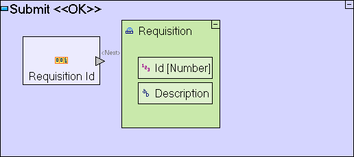
model. Name it Requisition Id.
)
and drop it into the Submit
model. Name it Requisition Id.
The model should look similar to the following:
Sequence Number is an
example of a built-in process (action) that generates a new
unique
identifier. A process is something that is being performed.
A process can be a built-in action
provided with the Tersus platform, and accessible through the
palette
(e.g. a basic mathematical calculation), or a more complex
process
modeled by a user (either you yourself or someone else).
Process modeling is the major
activity required for creating a solution (a solution is
comprised of
display models, data models and process models).
When
a
process (in our case Sequence Number) generates some
output
(the unique identifier), the output needs to “exit” the
process in order to be used by another process or populate a field
of
a data structure. An Exit slot is modeled as a gray
triangle
(![]() )
that appears on the frame of the process model.
)
that appears on the frame of the process model.
There are two major types of Slots: Triggers that receive data when a process starts (discussed later), and Exits that expose data generated by the process while executing.
The Sequence Number template outputs the unique identifier it created through the predefined <Next> exit.
Of course, we still need to pass this generated identifier from the <Next> exit of the Sequence Number process to the Id field of the Requisition data structure. To do this we shall use a Flow.
Select the Flow
tool (![]() )
at the top row of the palette, click on the <Next>
exit slot (
)
at the top row of the palette, click on the <Next>
exit slot (![]() )
of Requisition Id
to specify the Source,
and then click on the Id
field in Requisition
to specify the Target.
An arrow should appear linking the slot with the field.
)
of Requisition Id
to specify the Source,
and then click on the Id
field in Requisition
to specify the Target.
An arrow should appear linking the slot with the field.
While using the Flow tool, the mouse pointer changes to signify whether the current position can serve as the Source or Target of a flow definition.
The Submit model should now look as follows:
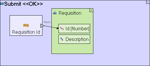
A Flow is modeled by an arrow between two model elements (Source and Target). A Flow defines the relation between the Source and Target, in two ways:
Order of Execution: When should each process be executed (and depending on what conditions).
Data Flow: When and how are data items passed.
Now that we've stored the automatically generated identifier in the Requisition data structure, we need to store the Description in the same data structure – after all, this is the real information we are interested in. To accomplish this we shall define a new type of element in the model called a Display Data Element.
A Display Data Element is an alternative representation of a Display element (and its sub-elements) as a data structure. It's main purpose is to provide access to the contents of the display so that it can be read from or written to.
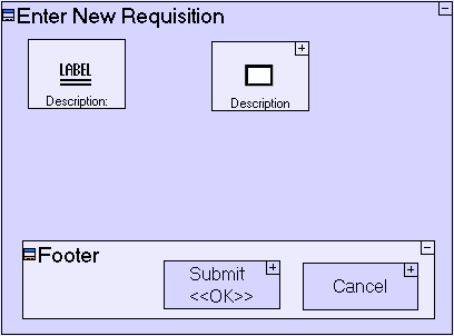
For example, look at the display hierarchy of the popup we are modeling, which contains a label, a text area, a footer and 2 buttons (see screenshot of the Display - below left). This is represented by a data structure of the popup, which contains data structures for the text area, button and label; the text area contains another data structure for its value (see screenshot of the Display Data Element - below right).
 |
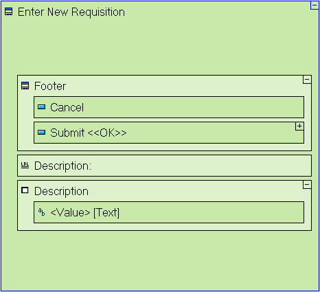 |
The order of display elements in the Display Data Element screen shot (above right) may be different from the one you see in your model. The order of appearance is defined by the order in which the elements were actually added. As long as all the elements appear (at any order) the runtime behavior will be consistent with the tutorial.
We would like to access the contents of the Description text area, and so we must add to the Submit button a Display Data Element that references the Enter New Requisition popup. Since Enter New Requisition is the “father” of the Submit button, we use the Add Ancestor Reference operation:
Right-click on the Submit
button, select Add
Ancestor
Reference from the menu, and select ![]() Enter New Requisition.
Enter New Requisition.
Notice that the inserted data structure has a blue frame (as opposed to the regular black frame of other elements). The blue frame indicates the fact that the data structure is a reference to another element (the Enter New Requisition popup), so that as data changes in one the change is automatically mirrored in the other.
Next you need to create a flow from the Description text area within Enter New Requisition to the Description field in the Requisition Data structure. The actual text entered by the user is available through the <Value> data element of the Description text area within Enter New Requisition data element:
Use the Flow
tool (![]() )
to link Enter New
Requisition/Description/<Value> to
Requisition/Description.
)
to link Enter New
Requisition/Description/<Value> to
Requisition/Description.
Most display elements contain default data elements through which they can be manipulated. These data elements are identified with a descriptive name (such as Value) surrounded by angled brackets (<...>).
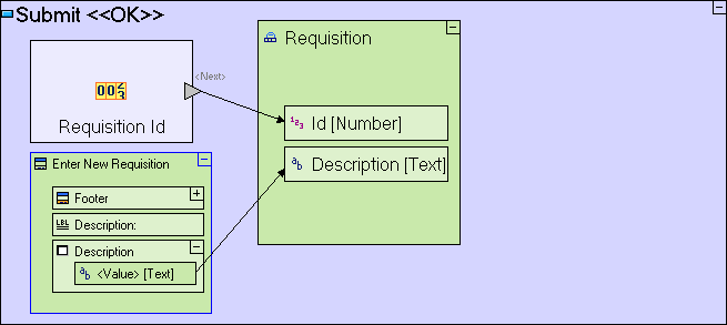
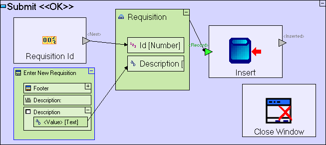
The Submit model should now look as follows:
Let’s summarize what this model does so far:
The Requisition Id sub-process generates an identifier that is passed to the Id field of Requisition, and the content of the Description text area (entered by the user) is passed to the Description field of Requisition.
Now that the Requisition data structure has been created and populated with the relevant data, the data has to be stored in the database. To accomplish this, we shall use another process template, Insert:
Select the Database/Insert
template (![]() )
and drop it next to the Requisition
data model.
)
and drop it next to the Requisition
data model.
The
Insert template includes a <Record> trigger
slot
(![]() )
through which it receives the data structure to be saved in the
database.
)
through which it receives the data structure to be saved in the
database.
Trigger slots are used as the entry point through which a process receives input data when its starts executing.
To send the Requisition data structure to Insert, let's create a flow:
Select the Flow
tool (![]() ),
then click on the Requisition
data structure (anywhere outside the Id
and Description
fields) to define it as the source of the flow, and then click
on the
<Record>
trigger of the Insert
model to define it as the target of the flow.
),
then click on the Requisition
data structure (anywhere outside the Id
and Description
fields) to define it as the source of the flow, and then click
on the
<Record>
trigger of the Insert
model to define it as the target of the flow.
The Submit model should look as follows:
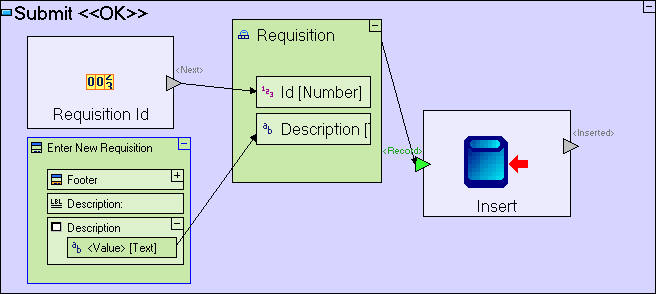
The meaning of the last change should be straight forward – the Requisition database record data structure is inserted as a new record to the database, into a database table with an identical name: Requisition. If the table does not exist in the database, it will be created automatically by the application server.
Notice that many slot names in templates (such as Sequence and Insert in the above screenshot) use a specific naming convention, where the name is surrounded by angled brackets (‘<…>’). These are reserved names on which template functionality may rely. If a reserved name is changed, the template may fail or function incorrectly.
Once the requisition has been written to the database, the popup window should close:
Select the Display Actions/Close Window
template (![]() )
and drop it into the Submit button.
)
and drop it into the Submit button.
The Submit model should look as follows:
The Submit model has 2 parts occurring in an unspecified order, one is the Close Window process, and the other is the chain of processes which saves the requisition data in the database.
Sometimes it is mandatory to specify which process occurs first, because the order of processes is an essential part of the application’s logic. In other cases the order in not important, but nevertheless, it is a good practice to make sure processes occur in a well defined order even when this is less critical.
We want to make sure that the Enter New Requisition popup window closes only after data has been saved, therefore we should define a flow which specifies that the Close Window process occurs following the Insert process, and only if insertion was successful.
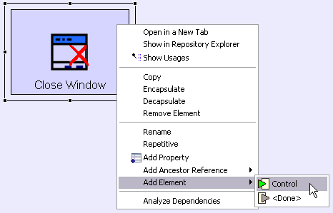
To do so, we must first add a trigger to Close Window. We can do so, either by adding a new trigger slot selected from the palette, or by taking advantage of the fact that Close Window is “hiding” a pre-defined trigger which is there for exactly that purpose:
Right-click
on the Close Window element,
open the Add Element
sub-menu, and select the ![]() Control trigger
element.
Control trigger
element.
The Submit model should look as follows:
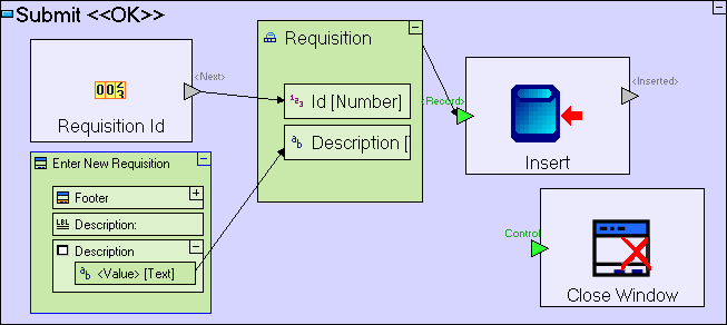
The “hidden” Control
trigger, is available due to the fact that the Close
Window
template is implemented as a Prototype.
Prototypes
define the elements making up a given model, and what parts
of it are
mandatory. In Close Window's
case the trigger is not required in order for Close
Window
to function (as demonstrated by
the Cancel button in
our popup), but in most use cases (such as the one we have
implemented here) the trigger is needed, and so it is
provided as an
optional element of the Close Window
prototype.
It
should be noted that the other templates are also
implemented
as prototypes. For Example: Insert's
prototype includes a “hidden” exit, <Duplicate>,
which is useful in cases where the record to be
inserted has a
duplicate key, in our case, if the Requisition data
structure
contains an Id which already exists in the database.
But as
this will never occur in our model (we are generating a unique
Id
using the Sequence Number template), the <Duplicate>
exit may remain “hidden”.
It
is important to point out that all
elements available through the Add Element
sub-menu are there for 'shortcut' purposes only. Each
element can
actually be created manually (in the specific case
that is by
dragging a trigger from the palette onto Close
Window,
and naming it Control),
and will work just as well.
We want to close the window only after the record has been inserted to the database, i.e. when Insert is successful and exits through the <Inserted> exit:
Select the Flow tool to link the <Inserted> exit of Insert to the Control trigger of Close Window.
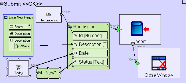
The Submit model should look as follows:
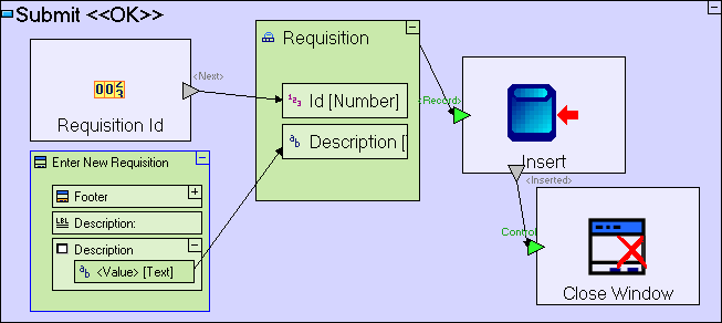
You may have noticed that the Insert/<Inserted> trigger in the preceding screenshot has been moved from its default position. This has been done to make the model more “readable” to the modeler, and has no effect on the model’s functionality.
Save your work.
To view the application in the browser:
Click the ![]() Launch the
application toolbar button.
Launch the
application toolbar button.
Try entering requisitions.
At this stage we still cannot see the content of the database to verify the requisitions have been successfully stored in it. We will model this later.
If you wish, you may use an external tool (usually provided by the DBMS vendor) to verify that the Requisition table has been created in the database and to view its content.
Import the sample project Tutorial 3-4 and use it as the basis for the next stage of the tutorial.
For a reminder on how to import a sample project, see the Importing a Sample Project section at the end of Stage 2.
This sample project contains all the functionality modeled thus far.
The sample project also includes additional functionality, as follows:
|
Functionality |
How to Model |
Located in |
|
Add fields to the Requisitions table for future use |
Add a Date field (drag the Data Types/Date template) Add a Status field (drag the Data Types/Text template) |
Requisition |
|
Set a default value (today's date) to the requisition's Date field |
Drag the Dates/Today template Define a flow from Today/<Today> to Requisition/Date |
Submit button |
|
Set a default value (New) to the requisition's Status field |
Drag the Constants/Text template Name it New Define a flow from “New” to Requisition/Status |
Submit button |
We have completed the modeling of the logic performed behind the scenes, retrieving user input and saving it in the database.
You may now proceed to Stage 4, in which we will implement a table display of all the requisitions stored in the Requisitions table.
Click here to open the live project in a separate window.